
Page 4 of 6
Home
3D Modeling for Paper Model Tutorial - Modeling 3D boat 2
- Details
- Written by: Julius Perdana
- Category: Tutorial
Article Index
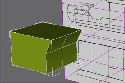
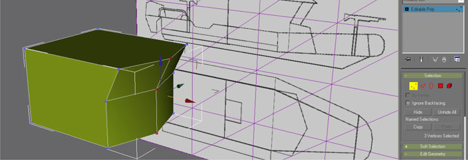
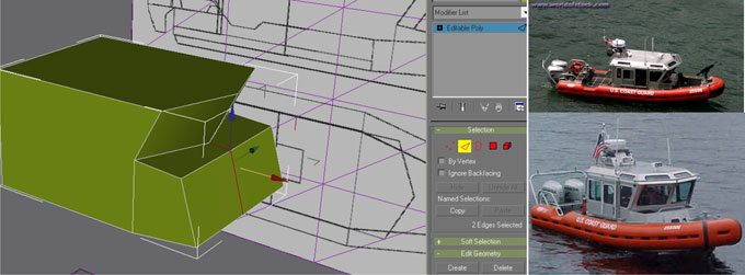
Also using the Slice Plane function I split again both surfaces but this time I rotate the slice plane 90 degree. Now we have 4 segments. Change selection to vertex again move all 3 vertex in the middle and pull out to match the blueprint on the side view [Front View = Press F]
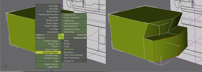
Also using the Slice Plane function I split again both surfaces but this time I rotate the slice plane 90 degree. Now we have 4 segments. Change selection to vertex again move all 3 vertex in the middle and pull out to match the blueprint on the side view [Front View = Press F]. Now we’re going to extrude the 2 bottom surfaces outward. Select polygon selection again then, select both bottom surfaces then right click and choose on TOOLS 2 - Extrude Polygon then pull out the surfaces.

Also using the Slice Plane function I split again both surfaces but this time I rotate the slice plane 90 degree. Now we have 4 segments. Change selection to vertex again move all 3 vertex in the middle and pull out to match the blueprint on the side view [Front View = Press F]. Now we’re going to extrude the 2 bottom surfaces outward. Select polygon selection again then, select both bottom surfaces then right click and choose on TOOLS 2 - Extrude Polygon then pull out the surfaces.
Adjust the geometry using edit vertex [ vertex selection] on front view. Change to Perspective view again to see the result. Now we look at our photo references, we don’t need the line in the middle on the extruded surfaces, we have to remove it. Change selection to Edge then select both lines or edges using Ctrl for selecting multiple objects. Then on edit geometry rollout on Modify tab, find Delete button then click it. Deleted edges always left unused vertex, we have to move the unused vertex overlap to the nearest vertex and weld them. Select both vertex and on the modify tab - edit geometry rollout - scroll down until you find Weld, then click selected, then we will have welded vertex.
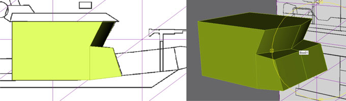
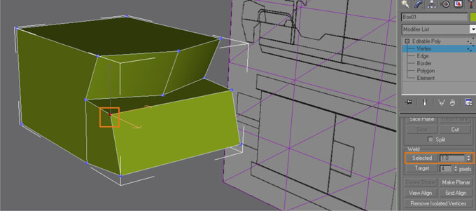
To match the real boat, I split again the front surface into 3 parts then push the outer vertex like shown on image below

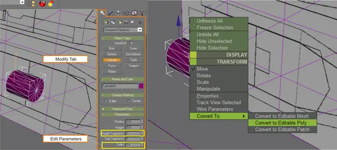
Create a cylinder : Create tab - Cylinder - edit Parameters with 1 height segment and 14 sides. Color your cylinder with purple and convert it into editable poly.
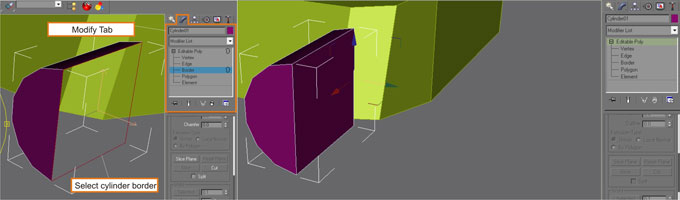
Select the top and bottom vertex shown below and connect both vertex by using Cut function as also shown below, right mouse click to stop the operation. Do same with the back of that cylinder. Then select edit polygon and select and delete the right side of the cylinder.

Change edit selection to border, click on the gap hole on the cylinder then right click and find Cap on TOOLS 2 , now we have a closed half cylinder. Click on the border again to end the selection and back to normal again.
Lastest gmax tutorial file download below
TO BE CONTINUED...
Click Next in this page to continue to Exporting 3D model to Pepakura